5

Нужные страницы

Translate

Search

понедельник, 9 октября 2017 г.

SmartMates in Solidworks

In Solidworks, you can simplify the interfacing of components. Press and hold "Alt" to move the mouse pointer to the desired surface, press the left mouse button and drag to the second surface for the auto-conjugation. A pane will appear with the default interface already selected for these surfaces. Those. if the surface is flat, then the automatic interface is a coincidence, if the surface is cylindrical, then the automatic interface is concentric. There are other options for automatic pairing


(SmartMates Procedures)
Desired Mate Action
What to Do
Mate two components already in the assembly. Press Alt and drag one component onto another.
Mate a new component while adding it to the assembly.Drag a part from another window onto another part in the assembly.

  • From a part file: Select an entity and drag.
  • From an assembly file: Hold down Shift, then select an entity and drag.
Fully mate a commonly-used component while inserting it in the assembly.Drag a part with mate references from Windows Explorer or the Design Library into the assembly. This method can fully mate a new component, but you must set up mate references beforehand.

Types of SmartMates
The mates added by the SolidWorks application depend on the situation.
    In most cases, the application creates one mate. The type of SmartMate created depends on the geometry used to drag the component, and the type of geometry onto which you drop the component.
    The application creates multiple mates under certain conditions:
  • If the application finds circular edges to mate, it creates a peg-in-hole SmartMate.
  • If the application finds circular edges and a circular pattern that matches on both components, in addition to the peg-in-hole SmartMate, it adds a concentric mate to line up the patterns on flanges ( useful for pipe fittings).


    For more information on auto-mates, see Solidworks Help.

    Quick add special symbols to Solidworks


    When filling in those. requirements it is necessary to put a symbol of diameter, plus-minus, degree, etc. Adding using the symbol table is not fast. And in the design it is desirable to optimize the routine work, it means the design of the drawings.
    For example, to insert a symbol from a symbol table, you need to go through three menus, and then select the one you need from a large number of fonts. Yes, there is a huge choice in the symbol table, but the designer does not need technical requirements for it, it needs quite a few special symbols.
    Solidworks - Добавление спецсимволов
     Adding special symbols


    Solidworks - Библиотека обозначений
    The Symbol Library
    Solidworks - Таблица символов
    The Symbol Table


    If you apply a dimension, the symbol of diameter and degree can be added quickly.
    Solidworks - Добавление диаметра в размер
    Adding a diameter

    then in the notes so simply does not work. It will be necessary to make quite a large number of mouse clicks until you get to the required symbol. Fortunately, there is the ability to quickly enter special characters using ALT-codes. To enter a special character, press and hold ALT to enter the numeric character code.
    List of most frequently used:


    English keyboard!
    (±); input: ALT+0177
    (°); input: ALT+0176
    (²); input: ALT+0178
    (³); input: ALT+0179 
    (Ø); input: ALT+0216
    (ø); input: ALT+0248 


    Of course, on this list of ALT-codes is not limited, the full list can be found in nete, on the same wikipedia.
    I think that to speed up the input to remember a few digital codes will not be difficult, try. Of course, you can enter some special characters using internal Solidworks codes such as <MOD-DIAM>, <MOD-DEG>, <MOD-PM>. What is the analog of diameter, degree and plus or minus. But the ALT code is shorter and easier to type.

    Macro for creating a spring

    The spring is one of the standard products, which is often used, but it is desirable to automate the simulation. Fortunately, there are enthusiasts who undertake this work. Macro for creating springs of tension and compression "SpringSW" - author of Shvg. To use the macro, you must add it to add-ins. To do this, open "SpringSW.dll", then "Spring" will appear in the "Tools" menu. Use the look at the video. For the coupling of the spring into the part, there is an axis "Axis1". The build tree is hidden, but it's even better. The spring has several configurations in different states: compressed, working, etc. The macro allows you to build compression springs and also to edit the data. Easy and convenient to use.


    Administrator rights are required to install and use the macro. You can change the shortcut to start


    Download macro с SpringSW

    пятница, 6 октября 2017 г.

    Localized interface in Solidworks

    Often, after the installation of the localized version of Solidworks user instead of Russian or Chinese, Polish (depending on the native language) interface sees the English interface. What to do? 

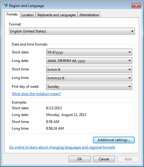
    Step 1. For the beginning it is necessary to check whether the set your locale (locale) in Windows.

    Region and Language Settings
    Region and Language Settings

    If not installed, install and run the solid. Did not help?


    Step 2.

    As a rule, it is sufficient in the settings Solidworks uncheck "Use English Language menus" (use the English menu) and restart Solidworks, so there was a Russian interface.

    Uncheck, so it was like on the screenshot below, click "OK" and restart Solidworks.

    Did not help? There is a way that will show who's boss :).


    Step 3.

    It is necessary to rename the folder with the Russian on the English language resources, and English to Russian (in fact the latter, at the discretion on any name). Folders with resources are default:

    versions prior to SolidWorks 2009

    "C:\Program Files\SolidWorks\lang\english" - English resources

    "C:\Program Files\SolidWorks\lang\russian" - Russian resources


    SolidWorks versions 2009 -2012

    "C:\Program Files\SolidWorks Corp\SolidWorks\lang\english"
    "C:\Program Files\SolidWorks Corp\SolidWorks\lang\russian"


    This procedure is available for other languages, respectively, you must rename the directory to the desired language, ie, French, German, Chinese, or some other.

    To change the language temporarily, you can use bat-files.

    Crashing Solidworks and the threshold of system resources

    I think everyone who modeled in Solidworks came across an unexpected program closure. Bouncing solid quite often, but as a rule, when complex models are opened and closed intensively or when they are saved, which is especially unpleasant.
    Do not all fall for the curvature of developers, they are trying to create a quality product. The reason for the unexpected collapse of Solidworks is the limitation of Windows that the process can only access 10,000 GDI objects.

    What is GDI?

    GDI objects are used to draw window elements that are not in the graphics area in SolidWorks. For maximum performance, the graphics area uses OpenGL, which gives more direct access to the equipment for video processing. GDI objects are used for the chrome graphic area, so every time a new document is opened, the number of GDI objects used by SOLIDWORKS will increase. Prior to this, SOLIDWORKS 2011 SP4, if the part was opened in the assembly and its own window, when this window was closed, it would not free these GDI objects. The default behavior is now to release these descriptors, but not all of them are released.

    Why is this all due to the failure of SOLIDWORKS? Windows has a default limitation that one process can access only 10,000 GDI objects. Because SolidWorks does not release all objects when the document is closed, the number it uses increases continuously with each new document and gradually approaches the limit set in Windows.


    Is it possible to use this knowledge to predict when SOLIDWORKS will knock out? 


    Predicting a SOLIDWORKS crashing

    As it was written above, this is not technically a failure, if SOLIDWORKS reaches the limit of 10,000 by object, Windows completes the process. This is not caused by a code error or by problems with shared memory access or anything else that causes a crash. It's just that Windows believes that SOLIDWORKS consumes too much resources and closes it to get those resources back. But since there is a certain number at which it closes, you can predict when it will happen. In fact, it's easy to control. Just follow these steps:


    • Open task manager (you can right click on the task bar and click task manager). 
    • Click View, Select Columns…
    Select Columns in Windows Task Manager


    Check off GDI and User Objects and click OK

    Display GDI Objects
    Now, the task manager will display the current value of the GDI and USER objects for each process


    Display GDI Objects
    Display GDI ObjectsIf a part is opened and closed several times the number of GDI objects it uses does not increase. SOLIDWORKS releases all handles every time.  The same applies to assemblies as well.  The problem is only encountered when a part is open in an assembly and it is opened in its own window and then closed.  
    How to troubleshoot this crash problems

    How can this problem be avoided? Do not keep your assemblies open unless you need them to be, and monitor your task manager periodically to see how many objects you are using.  Closing SOLIDWORKS and opening it will reset this count.  Furthermore you can increase the maximum number of GDI Objects a process can use by following these settings:
    • HKEY_LOCAL_MACHINE\SOFTWARE\Microsoft\Windows NT\CurrentVersion\Windows\GDIProcessHandleQuota 

    • Sets the number of GDI objects, the range of values is 256 ~ 65536, the default is 10,000.


    • HKEY_LOCAL_MACHINE\SOFTWARE\Microsoft\Windows NT\CurrentVersion\Windows\USERProcessHandleQuota 

    • Sets the number of descriptors, the range of values is 200 ~ 18000, the default is 10 000.
    Increase the values and reduce the risk of Solidworks failure. When changing the parameters, switch to the decimal system of the calculus.

    P.S.
    When writing an article for testing, the parameters were reduced to 1500, after the Solidworks Resource Monitor warning, after some time the Solidworks was crashed. 

    The same manipulations apply only to the GDI problem, if SolidWorks Resource Monitor writes that there is not enough memory, then the problem will be to add RAM or unload other programs.


    By the materials of the blog javelin-tech

    test